
LED Light Bulb Repair Guide
Friday
Add Comment
A LED light bulb is a modern and efficient light source. LED bulbs
are safe – they do not contain mercury or other toxic elements and do
not cause harm when they are broken. However, the first thing that
encourages us to buy these bulbs is their cost efficiency due to low
electricity consumption. What’s more, LED devices are rather reliable
and usually serve all their lifetime. Thus, the advantages of this light
source are evident: it’s bright and serves long.
Traditional incandescent light bulbs cannot be repaired at all, while
in LED bulbs you can repair almost everything. You just need to find
the malfunction, make some repair and prolong your light bulb lifetime.
If you are familiar with repair operations you can even find all
necessary tools at home; all you need is to find some time for that.

LED bulb operation is based on the abilities of some materials to
emit light under certain conditions. The working element of the bulb, a
light emitting diode is a semiconductor device that emits incoherent
light when electric current runs through it. LEDs emit light only if you
use DC current.
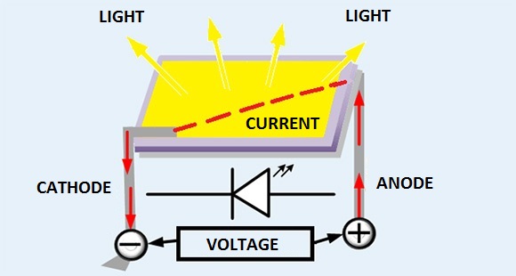
How does a light emitting diode work?
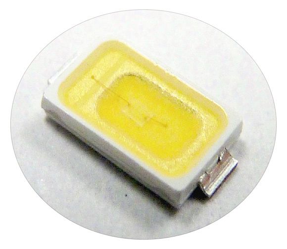
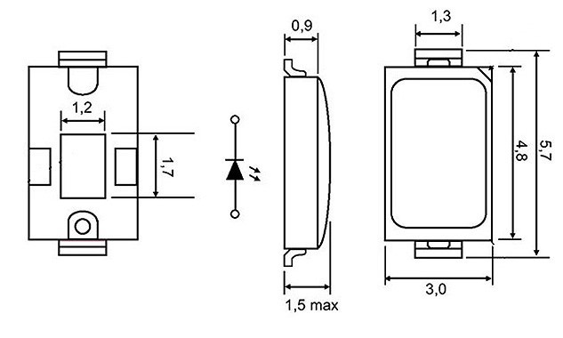
Let’s use a popular SMD LED in the 5730 housing to illustrate the LED operation.
You can find its specifications below:
| Peak direct current (IFPM) | 260 mA |
| Direct current (IFM) | 180 mA |
| Reverse voltage (VR) | 5 V |
| Dissipation power (PD) | 0,63 W |
| Beam angle | 120° |
| LED lens type | transparent |
| Operation temperature (TOPR) | -40°C – +85°C |
| Storage temperature (TSTG) | -40°C – +100°C |
| Soldering temperature (TSOL) | 260°C |
To put it simply, a LED transforms the electric current into light
emission. This light source consists of a semiconductor crystal on a
non-conductive base, a housing with contacts and an optical system. To
increase LED stability the space between the crystal and the plastic
lens is filled with transparent silicon. Aluminum base reduces
overheating. Under normal conditions heat emission is low.
The more current runs through the diode, the brighter it lights.
However, due to internal resistance of p-n transition, the diode heats
up and under high current it may burn out – the connection conductors
melt and the semiconductor burns. Thus, to ensure the needed current
value, a bulb should contain a power supply – a driver, and a heat
dissipation system – a heatsink.
Now let’s have a closer look at the bulb.
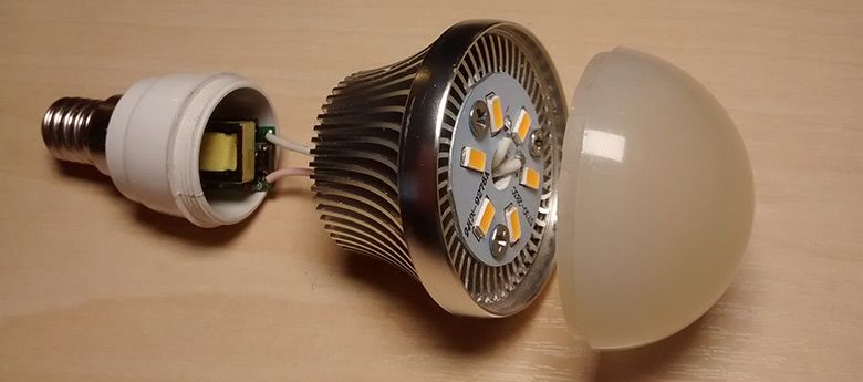
LED bulb main parts
- Dissipator. It reduces the irregularity of a light flow and extra lightness of some emitting elements. It also ensures lighting under a certain angle (for household lamps it should be wider).
- PCB with LEDs. A board on the aluminum base that contains LEDs. The amount of LEDs is very important for heat exchange; therefore, it should correspond to the bulb design. There is thermal paste between the PCB and the heatsink to increase heat transfer.
- Heatsink. A quality heatsink is designed for heat withdrawal from bulb components. It is used to prevent LEDs from overheating. Heatsink ribs make heat withdrawal and dissipation more effective.
- Bulb cap. It is screwed into the lamp socket and ensures a reliable contact. Caps are mostly made of copper-zinc alloy with nickel coating. To ensure protection against electricity current breakdown caps of most LED bulbs have a polymer basis.
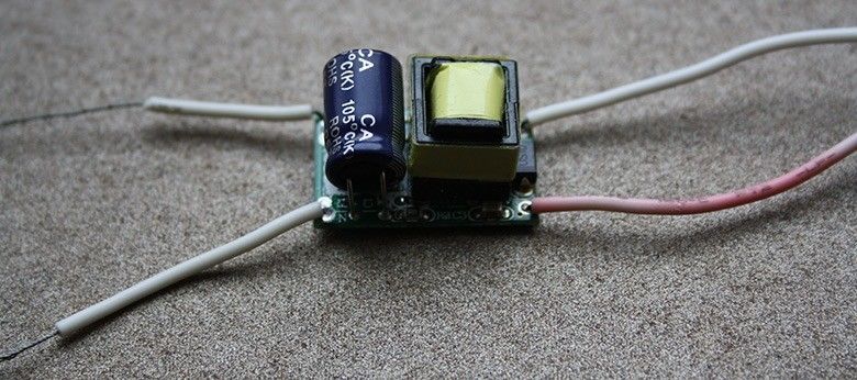
- Driver. This is an electronic circuit diagram designed for transducing AC current into DC current of a required value. Excessive current leads to LED burnout. A quality driver ensures bulb operation during voltage jumps and LED operation with no pulsation.There are a lot of circuit designs for LED drivers. We demonstrate only a couple of them:
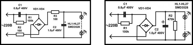

There are simple drivers where voltage is limited by a resistor or capacitor, as well as more advanced drivers using microchips. This type of drivers not only limits voltage but also ensures the optimal power consumption and performs protection functions. Drivers with microchips are more modern and efficient but more difficult to produce and, therefore, more expensive.
Bulb operation and troubleshooting
The bulb operation principle is rather simple: AC current is provided
from electricity line to the driver through contact wires, where it
becomes DC and runs through LEDs that transforms it into light. The heat
is withdrawn using a board containing LEDs and a heatsink.
LED bulbs first seem different, but they have a similar design and are made using the same principles. If you master repairing just one bulb, it will be much easier to fix the next ones.
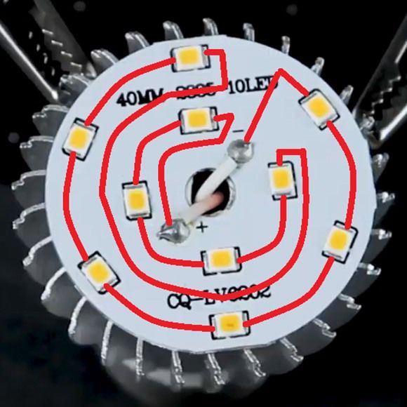
Most modern bulbs have SMD LEDs connected in series as a light source. The circuit design is in the picture on the left.
If one of diodes is dead, the rest won’t work. The most common
failure reason is LED burning out (in most cases only one of them).
However, sometimes several LEDs fail at the same time.
LEDs may burn for different reasons. Among them are the low component
quality, absence of current stabilization, LED overheating, and voltage
jumps. Some manufacturers overload LEDs to make customers interested in
high brightness of a small bulb.
However, in most cases it is possible to fix the LED light bulb.
Moreover, the repair may be conducted even by an amateur. And the cost
is lower than that of a new bulb.
To find out the failure cause you should disassemble the bulb – take
off the dissipator and reach the inside. It may be glued to the housing
so you may need to use a thin screwdriver to do that. It’s often the
case that bulbs with a glass dissipator cannot be disassembled.
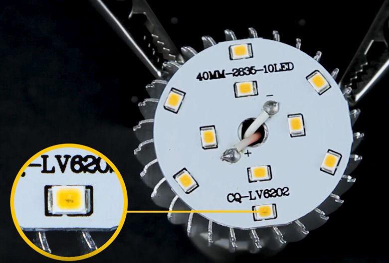
There is a board with LEDs inside. High-quality bulbs have only LEDs
on this board. If there are some other components, it will overheat
faster and the components will fail.
Next comes a visual inspection. You may locate the burnt LED just finding the black spot of some burning marks.

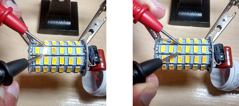
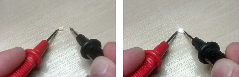
In some cases, however, the LED may look undamaged. Then you can test
and find a faulty LED using a multimeter. Most of modern multimeters
have a diode test function. The test procedure is as follows: touch the
anode with the red probe and the cathode with the black one. The working
diode will light. If you change the probe polarity, the meter will
display “1” and the diode won’t light. Neither will a faulty diode light
during the test.
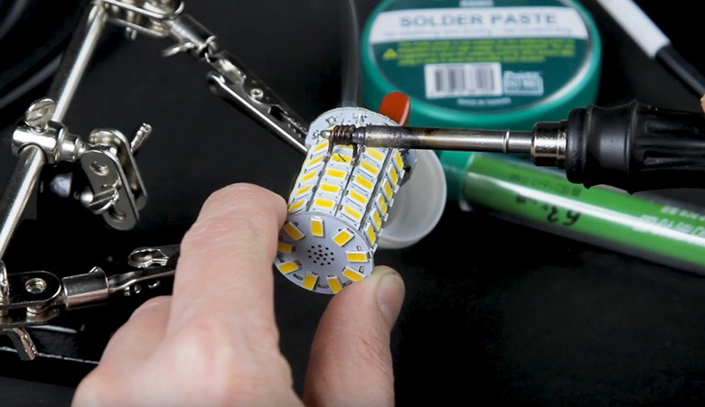
LED replacement
Now when you have found a faulty diode, it has to be changed. It is
soldered to the board. Overheating hazards are critical in diode
operation. Keep in mind that soldering recommendations are included in
diode technical specifications. For example, for 5730 SMD LED, which is
widely used due to a good balance of size, power and light flux, the
soldering temperature is 260°C (no more than 2 seconds).
If the bulb design allows, you should take the board off the
heatsink, desolder driver contacts and after that start changing the
LED. The board may be fixed using a PCB holder (we then have both hands
free). If possible, heat it up from below with a hot air gun. The
temperature shouldn’t be high, about 100 ÷ 150°C, in order not to damage
the working diodes.
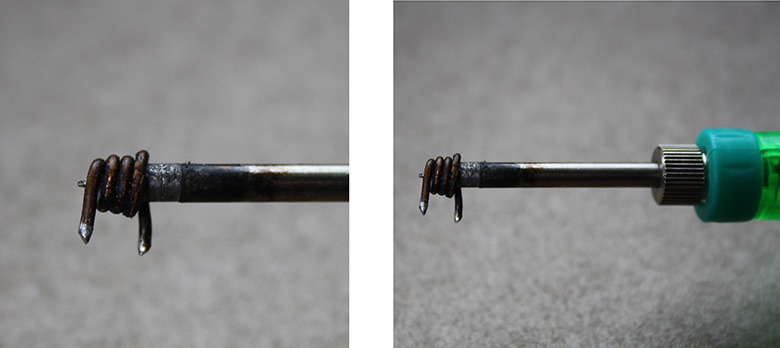
It is convenient to take off the old LED with hot tweezers that heat
up both outputs at the same time. Or you may do it with a self-made
simple analogue – a copper conductor twisted around the soldering iron
tip.
You should replace the old LED with a new one of the same type. You
may usually find LED marking on the bulb PCB. Mind the polarity during
installation.
There is a seemingly easier way to repair the LED – just install the
conductor instead of the damaged diode, that is, connect the contact
pads. It looks like this:
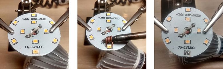
If there are a lot of LEDs on the PCB and they are all installed in
series, one of them missing won’t greatly affect the others. However,
the voltage on the working diodes will be higher and the chances for
them to burn are higher. There is no such risk with high-quality bulbs,
where the driver sets the required current and reduces the voltage to
the level safe for LEDs.
Other failures
If all the diodes turned out to be working during the test, you
should check the bulb driver and search for other damage, as well as
check the conductors and contacts for discontinuity.
The driver in quality bulbs should be a separate PCB and be located
in the bulb cap. Each manufacturer has a unique driver circuit design,
so there are no standard repair recommendations. You should apply an
individual approach here.
You should test the main components with a multimeter, check the
diodes and transistors for shortage, compare the resistor values, change
the capacitors that lost their capacity. If there is an IC chip in the
driver circuit, you should check the voltage on its outputs according to
its technical specifications and decide if it’s working OK. Change the
faulty components if needed.
Finally check if the disassembled bulb works fine and then assemble
it. You may need to apply thermal paste, tighten the screws, and fix the
dissipator.

No comment